GEODETIC AND CONTROL SURVEY SERVICES IN AFRICA
Geodetic Surveys entail locating and relating the position of objects on the earth relative to each other, while taking into account the size, shape and gravity of the earth. This type of survey is suited for large areas and long lines and is used to find the precise location of basic points needed for establishing control for other surveys. Horizontal and vertical networks that span the country form the primary spatial reference system used in mapping, boundary demarcation, and other geomatics applications. Practical applications of geodesy include monitoring earth movement and determining the precise location of points on the surface of the earth, for use in satellite tracking and global navigation.
Control Surveys encompases the positioning of survey ground points by using GPS or GNSS as per the specifications for intended uses. The extension of GPS/GNSS geodetic control networks to remote areas, Establishment of Survey Control Networks for offshore and underground surveys among others.
Survey control networks are the fundamental foundation to support any project from building construction, deformation monitoring, to the national survey network for legal boundaries, geographical information and mapping. The diagrams below show establishment of horizontal controls using traversing method and vertical controls using levelling method.
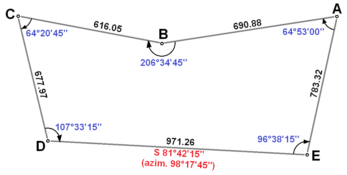

Traversing Survey Method
Traversing is that type of survey in which a number of connected survey lines form the framework and the directions and lengths of the survey lines are measured with the help of an angle measuring instrument and tape or chain respectively. There are two types of traverse surveying i.e. Closed Traverse and Open Traverse. The closed traverse is suitable for locating the boundaries of lakes, woods, etc and for a survey of large areas. the open traverse is suitable for surveying a long narrow strip of land as required for a road of the canal or the coastline. Traverse networks involve placing survey stations along a line or path of travel, and then using the previously surveyed points as a base for observing the next point. Traverse networks have many advantages, including: The main instruments used for levelling include but not limited to:
- Less reconnaissance and organization needed;
- While in other systems, which may require the survey to be performed along a rigid polygon shape, the traverse can change to any shape and thus can accommodate a great deal of different terrains;
- Only a few observations need to be taken at each station, whereas in other survey networks a great deal of angular and linear observations need to be made and considered;
- Traverse networks are free of the strength of figure considerations that happen in triangular systems;
- Scale error does not add up as the traverse is performed. Azimuth swing errors can also be reduced by increasing the distance between stations.
Levelling Survey Method
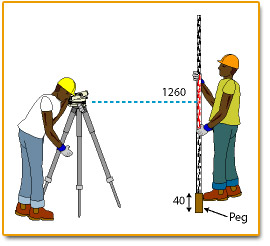 Levelling is a process of determining the height of one level relative to another. It is used in surveying to establish the elevation of a point relative to a datum, or to establish a point at a given elevation relative to a datum. The basic concept of leveling involves the measurement of vertical distance relative to a horizontal line of sight. Hence it requires a graduated staff for the vertical measurements and an instrument that provides a horizontal line of sight.
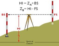
There are two accepted methods of booking observations – Rise and Fall method and Height of the Plane of Collimation method (HPC/HOC). Neither method can be said to be more accurate than the other. Rise and Fall does have an additional check on the arithmetical reduction of the observations which makes it more popular on line levelling. The HPC method is used for setting out because one always needs to know the height of the instrument.
Levelling is a process of determining the height of one level relative to another. It is used in surveying to establish the elevation of a point relative to a datum, or to establish a point at a given elevation relative to a datum. The basic concept of leveling involves the measurement of vertical distance relative to a horizontal line of sight. Hence it requires a graduated staff for the vertical measurements and an instrument that provides a horizontal line of sight.
There are two accepted methods of booking observations – Rise and Fall method and Height of the Plane of Collimation method (HPC/HOC). Neither method can be said to be more accurate than the other. Rise and Fall does have an additional check on the arithmetical reduction of the observations which makes it more popular on line levelling. The HPC method is used for setting out because one always needs to know the height of the instrument.
- Dumpy level: Often a generic term for an optical level. Dumpy level is commonly used leveling instrument to locate the points in same horizontal plane.
- Tilting level: Replaced by the automatic level but useful where vibration is a problem.
- Automatic level: Includes an internal pendulum which allows a horizontal reading.
- Laser level: This is a control tool consisting of a rotating laser beam projector that can be affixed to a tripod.
- Digital level: Staff read automatically.
- Water level: It is useful in confined spaces. The device utilizes the surface of liquid water in a pipe to establish a horizontal plane of reference.
Levelling Procedures
- Setting Up: Backsight and foresight distances should be approximately equal to avoid any errors due to collimation, refraction or earth curvature. The distances must not be so great as to not be able to read the graduations accurately. The points to be observed must be below the level of the instrument, but not lower than the height of the staff.
- Elimination of Parallax: Parallax is the apparent movement of the image produced by movement of the observer's eye at the eyepiece. It is eliminated by focusing the telescope on infinity and then adjusting the eyepiece until the cross-hairs appear in sharp focus. The setting will remain constant for the particular observer's eye.
- Booking:
- Level books or loose-leaf levelling sheets shall be numbered and indexed in a register.
- Details of the site, work, date, observer, chainman, booker, weather, wind, instrument and any other relevant items shall be entered.
- Enter the first observation (which is on a known point) in the Backsight column, and sufficient detail in the Remarks column to identify it. Enter the point's R.L. zero from the site register or plate on the BM, etc.
- Enter all other points on subsequent lines as intermediates except the point chosen as the foresight. Identify them in the Remarks column as above. Enter the foresight on a further line in the Foresight column.
- Change the instrument to the next setup. Enter the following backsight on the same line as the previous foresight but in the Backsight column.
- Repeat the above procedure at each setup on the outward run then reverse it to work back to the starting point on the return run. The furthest point out is treated as for all other change points.
- Calculate the rises and fall between successive points and book them in the appropriate column (one can determine whether each shot is a rise or fall by the following rule of thumb: a higher value on top denotes a rise; a higher value on the bottom denotes a fall).
- Add up the backsight and foresight columns for the entire traverse and note the difference between them; this is the close.
- Add up the rises and falls for the entire traverse, and compare the difference between them with the difference between the backsights and foresights; they should be the same.
- Carry the reduced levels in the R.L. column down the page by adding or subtracting the appropriate rise and fall values to the successive values of R.L. The final value of the original starting point will differ from the original value by the amount of the close.
Reducing the Levels
Two methods are in general use i.e. the "rise and fall" method and the "height of collimation" method. The latter reduces levels relative to the instrument height. As it has inferior in-built checks it should not be used and will not be covered here. The "rise and fall" methods shall be used for reduction of all site levelling. Reduction shall be carried out on site before packing up to ensure that the levelling has been done correctly.
If the levelling has been done correctly and all arithmetic reductions are correct, the differencesbetween total backsights and foresights, total rises and falls, and starting and finishing R.L.'s should be the same. This difference is the close; and for site inspection purposes it should be within ± 2mm or ± 6mm, depending upon which water-level standard is being followed, ± 3mm or ± 10mm.
Level Books
All levelling need to be booked in either level books or levelling sheets which shall be retained as permanent records. Level books shall be numbered so that they can be referenced on station history and inspection forms. They should be stored in fire-proof storage as for original record. They should also include an index. Levelling sheets shall be filed in time-sequential order in site files, and also need to be in fire-proof storage as for level books.
You can also request a quote for land, cadastral or mutation survey by sending us an e-mail at: geo@orbital.co.ke or call us on: +254-719-672296.